DUAL PROGRAMMABLE FREQUENCY FILTER
Digitally Programmable Filters
AD Dual Function Series
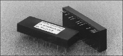
Our AD-Dual filters require a minimum set up procedure with no clock
and external components required. Two filter channels are available in the
same package to save valuable PCB space and wiring. Stable DC shift between
settings and wide cut off selections up to 1 MHz will greatly improve systems
resolution and signal to noise ratio. TTL/CMOS digital inputs are compatible
with most common microprocessors. |
 |
 Features include:
DUAL FILTER FUNCTION
Choice of two LOWPASS, or two HIGHPASS, or
one HIGHPASS and one LOWPASS
INDEPENDENT OPERATION
Frequency is programmed individually.
Separate Input & Output pins.
8 BITS, 10 BITS, & 12 BITS RESOLUTION
Frequency range of 1 : 255, 1 : 1023, & 1 : 4095.
ANALOG ACTIVE FILTER
RC active filter. Not switch-capacitor filter.
COMPLETELY ASSEMBLED
Fully finished module. No external component required.
CMOS, TTL & µP COMPATIBLE
Interface with 8 Bits (8085 & 6800),
and 12 Bits (68000) microprocessor.
4 STANDARD RESPONSES
Butterworth, Bessel, Chebyshev, & Elliptic.
|
BANDPASS & BAND-REJECT CONFIGURATION
Obtain BANPASS by connecting a HIGHPASS to a
LOWPASS in series, or a BAND-REJECT by connecting
a HIGHPASS and LOWPASS to a summer.
HIGH ATTENUATION, FAST ROLL-OFF
Filter orders from 2nd order to 8th order.
STABLE OUTPUT
Unity gain output.
Amplification available. (Up to 1000 times).
IDEAL FUNCTION BLOCK
High input impedance.
Low output impedance.
COMPENSATED DC OFFSET
Internal DC offset < 2 mV.
External adjustable to 0.0.
BUILT-IN DECOUPLING
Internal power supply decoupling.
|
Suggested Applications for AD & AD-Dual Models MC6800
Interface
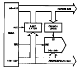
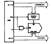
INTERFACE WITH 8 BIT PROGRAMMABLE FILTER
MC6800 Interface |
8085A Interface |
|
 |
 |
 |
| |
|
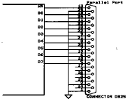
PROGRAM FREQUENCY VIA PRINTER PORT |
|
Case Style & Outline Dimensions
|
PIN ASSIGNMENTS
| Pin No. |
|
Model AD8D |
|
1 |
Digital Bit 2 (filter 1) |
|
2 |
Digital Bit 1 (filter 1) |
|
3 |
Digital Bit 0 (filter 1); (LSB) |
|
4 |
CS (filter 1) |
|
5 |
WR (filter 1) |
|
6 |
N/C |
|
|
7 |
Filter Input1 (filter 1) |
|
8 |
N/C |
|
|
9 |
V + (+15V) |
|
10 |
Filter Output2 (filter 2) |
|
11 |
DC Offset (filter 2) |
|
12 |
Ground |
|
13 |
Digital Bit 7 (filter 2); (MSB) |
|
14 |
Digital Bit 6 (filter 2) |
|
15 |
Digital Bit 5 (filter 2) |
|
16 |
Digital Bit 4 (filter 2) |
|
17 |
Digital Bit 3 (filter 2) |
|
18 |
Digital Bit 2 (filter 2) |
|
19 |
Digital Bit 1 (filter 2) |
|
20 |
Digital Bit 0 (filter 2); (LSB) |
|
21 |
CS (filter 2) |
|
22 |
WR (filter 2) |
|
23 |
N/C |
|
|
24 |
N/C |
|
|
25 |
Filter Input2 (filter 2) |
|
26 |
V - (-15V) |
|
27 |
DC Offset (filter 1) |
|
28 |
Filter Output1 (filter 1) |
|
29 |
Ground |
|
|
(all GND pins are connected) |
|
30 |
Digital Bit 7 (filter 1); (MSB) |
|
31 |
Digital Bit 6 (filter 1) |
|
32 |
Digital Bit 5 (filter 1) |
|
33 |
Digital Bit 4 (filter 1) |
|
34 |
Digital Bit 3 (filter 1) |
|
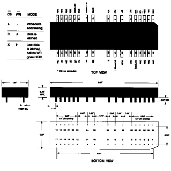 
WRITE CYCLE TIMING DIAGRAM |
Specifications
| ELECTRICAL CHARACTERISTICS |
| (Supply = ±15V., Load = 10 k‡, Temp.
= 25°C) |
|
Supply Current |
25 mA/4th order |
|
Input Impedance |
> 500 kohm |
|
Output Impedance |
< 1 ohm (@ DC) |
|
Cut-off Variation |
± 2% |
|
Frequency Stability |
0.01 % /°C |
|
Unity Gain Output |
0.0 dB |
|
Max. Input Voltage |
±12 V. |
|
Max. Output Voltage |
±12 V. |
|
DC Offset |
< ±2mV |
| MECHANICAL CHARACTERISTICS |
|
Dimension |
3.25" x 1.07" x 0.4" |
|
Pin Diameter |
0.025" |
|
Materials |
Glass Filled Thermoplastic Nylon |
|
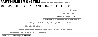
| OPTIONS |
|
Suffix |
Description |
|
L |
Low power consumption (20mA) |
|
I |
Industrial temp. range (-25° C to 85° C) |
|
M |
Military temp. range (-55° C to 125° C) |
|
A1 |
10x amplification |
| |
A2 |
100x amplification |
| |
A3 |
1000x amplification |
|
| About Us |
Product Index | Avens, Inc.
P.O. Box 518 Plumsteadville,
PA 18949
800-394-5407
Tel: 215-766-8775
info@avens-filter.com •
www.avens-filter.com
|


