PROGRAMMABLE FREQUENCY MODULE
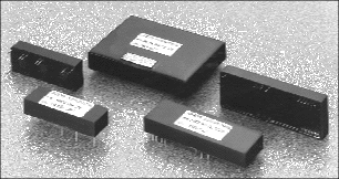
AD Series - Module Filters
Digitally Programmable Filters
Our easy to use AD Series filter modules need no external components.
Cut-off frequency can be precisely selected via TTL/CMOS digital inputs.
Units operate up to 1 MHz with resolution up to 16 Bits. The outstanding
feature of low
DC shift between settings is ideal for automation and multi-channel data
acquisition. |

Model AD2/AD3 Typical package outline shown
on page 7, AD8/AD10 shown opposite |
Features and Selection Tables
Model AD2
Miniature 2 BIT, 4 SETTINGS Features
- 2 BIT CMOS, TTL compatible
- Independent or binary weighed
- 4th or 8th orders
-
Binary Bit |
Selection Schemes |
| 2 |
1 |
A |
B |
C |
D |
| 0 |
0 |
0F0 |
0F0 |
0F0 |
F0 |
| 0 |
1 |
2F0 |
2F0 |
2F0 |
F1 |
| 1 |
0 |
4F0 |
F1 |
3F0 |
F2 |
| 1 |
1 |
8F0 |
2F1 |
4F0 |
F3 |
|
Model AD3
3 BIT, 8 SETTINGS Features
- 3 BIT CMOS, TTL compatible
- 8 independent frequency settings
- Butterworth, Bessel, Chebyshev, Elliptic, & Linear Elliptic
Binary Bit Selection Schemes
Binary Bit |
Selection Schemes |
| 3 |
2 |
1 |
|
A |
|
B |
|
C |
D |
| 0 |
0 |
0 |
F0 |
F0 |
F0 |
F0 |
| 0 |
0 |
1 |
2F0 |
2F0 |
2F0 |
F1 |
| 0 |
1 |
0 |
4F0 |
F1 |
3F0 |
F2 |
| 0 |
1 |
1 |
8F0 |
2F1 |
4F0 |
F3 |
| 1 |
0 |
0 |
16F0 |
F2 |
5F0 |
F4 |
| 1 |
0 |
1 |
32F0 |
2F2 |
6F0 |
F5 |
| 1 |
1 |
0 |
64F0 |
F3 |
7F0 |
F6 |
| 1 |
1 |
1 |
128F0 |
2F3 |
8F0 |
F7 |
|
Model AD8
8 BIT, 255 CONTINUOS STEPS w/Memory Features
- uP compatible
- 255 continuous steps
- Instantaneous selection
- Customer specified frequency
- Latching available for memory
| Fmax (Hz) |
Step size (Hz) |
Fmin (Hz) |
|
1,020.0 k |
|
4,000.0 |
|
4,000.0 |
|
510.0 k |
|
2,000.0 |
|
2,000.0 |
|
255.0 k |
|
1,000.0 |
|
1,000.0 |
|
102.0 k |
|
400.0 |
|
400.0 |
|
51.0 k |
|
200.0 |
|
200.0 |
|
25.5 k |
|
100.0 |
|
100.0 |
|
12.7 k |
|
50.0 |
|
50.0 |
|
10.2 k |
|
40.0 |
|
40.0 |
|
5.1 k |
|
20.0 |
|
20.0 |
|
2,550.0 |
|
10.0 |
|
10.0 |
|
1,275.0 |
|
5.0 |
|
5.0 |
|
1,020.0 |
|
4.0 |
|
4.0 |
|
510.0 |
|
2.0 |
|
2.0 |
|
255.0 |
|
1.0 |
|
1.0 |
|
25.5 |
|
0.1 |
|
0.1 |
|
Model AD10
10 BIT, 1023 STEPS DIP Switch Input Features
- 10 BIT Built-In DIP Switch
- No external binary bus needed
- No latching required
- Frequency set by internal DIP switch
- Support all filter functions
- Implement most filter responses
| Fmax (Hz) |
Step size (Hz) |
Fmin (Hz) |
|
102.4 k |
|
100.0 |
|
100.0 |
|
51.2 k |
|
50.0 |
|
50.0 |
|
20.5 k |
|
20.0 |
|
20.0 |
|
10.2 k |
|
10.0 |
|
10.0 |
|
5,120.0 |
|
5.0 |
|
5.0 |
|
2,050.0 |
|
2.0 |
|
2.0 |
|
1,024.0 |
|
1.0 |
|
1.0 |
|
102.4 |
|
0.1 |
|
0.1 |
|

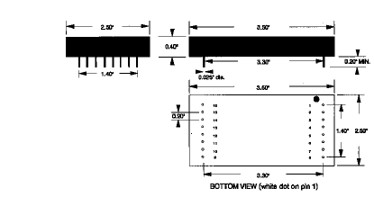
Case Style & Outline Dimensions
|
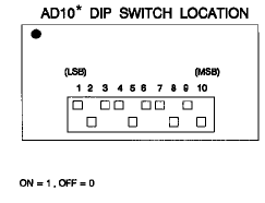
MODEL AD10 DIP SWITCH POSITION*
| 1 2 3 4 |
5 6 7 8 |
9 10 |
Frequency |
| 1 0 0 0 |
0 0 0 0 |
0 0 |
512 |
| 0 1 0 0 |
0 0 0 0 |
0 0 |
255 |
| 0 0 1 0 |
0 0 0 0 |
0 0 |
128 |
| 0 0 0 1 |
0 0 0 0 |
0 0 |
64 |
| 0 0 0 0 |
1 0 0 0 |
0 0 |
32 |
| 0 0 0 0 |
0 1 0 0 |
0 0 |
16 |
| 0 0 0 0 |
0 0 1 0 |
0 0 |
8 |
| 0 0 0 0 |
0 0 0 1 |
0 0 |
4 |
| 0 0 0 0 |
0 0 0 0 |
1 0 |
2 |
| 0 0 0 0 |
0 0 0 0 |
0 1 |
1 |
|


*TOP VIEW (white dot on pin 1)
Shown for AD10 model only |
PIN ASSIGNMENT
| Pin No. |
Model: AD3 |
Model: AD8 |
Model: AD10 |
| 1 |
|
N/C* |
Filter Input |
|
Filter Input |
| 2 |
|
N/C |
+15V |
|
Ground |
| 3 |
|
N/C |
-15V |
|
V+ |
| 4 |
|
Ground |
Ground |
|
Bit 9 (MSB) |
| 5 |
|
Filter Input |
Bit 7 (MSB) |
|
Bit 8 |
| 6 |
|
Bit 1 |
Bit 6 |
|
Bit 7 |
| 7 |
|
Bit 2 |
Bit 5 |
|
Bit 6 |
| 8 |
|
Bit 3 |
Bit 4 |
|
Bit 5 |
|
| Pin No. |
Model: AD3 |
|
Model: AD8 |
Model: AD10 |
| 09 |
|
+15V |
Bit 3 |
|
Bit 4 |
| 10 |
|
-15V |
Bit 2 |
|
Bit 3 |
| 11 |
|
Ground |
Bit 1 |
|
Bit 2 |
| 12 |
|
N/C |
Bit 0 (LSB) |
|
Bit 1 |
| 13 |
|
DC Adjust |
Ground |
|
Bit 0 (LSB) |
| 14 |
|
Filter Output |
DC Adjust |
|
V- |
| 15 |
|
N/C |
WR |
|
DC Adjust |
| 16 |
|
N/C |
Filter Output |
|
Filter Output |
|
*N/C: No Connection |
Specifications
ELECTRICAL CHARACTERISTICS
(Supply = ±15V., Load = 10 k‡,
Temp. = 25°C)
| Parameters |
AD2 |
AD3 |
AD8 |
AD10 |
| Filter Type |
Analog RC |
Analog RC |
Analog RC |
Analog RC |
| No. of BITS |
2 |
3 |
8 |
10 |
| Frequency Settings |
4 |
8 |
255 |
1023 |
| Control Format |
Binary |
Binary |
Binary |
Built-In DIP Switch |
| Logic |
CMOS, |
CMOS, |
CMOS, |
CMOS, |
|
TTL compatible |
TTL compatible |
TTL compatible |
TTL compatible |
| Supply Voltage |
± 15 V. |
± 15 V. |
± 15 V. |
± 15 V. |
| Supply Current |
20 mA/4 pole |
20 mA/4 pole |
30 mA/4 pole |
30 mA/4 pole |
| Input Impedance |
> 500 kohm |
> 500 kohm |
> 20 kohm |
> 20 kohm |
| Output Impedance(DC) |
< 1.0 ohm |
< 1.0 ohm |
< 1.0 ohm |
< 1.0 ohm |
| Maximum Input Voltage |
± 12 V. |
± 12 V. |
± 12 V. |
± 12 V. |
| Output Swing(2k load) |
± 12 V. |
± 12 V. |
± 12 V. |
± 12 V. |
| DC offset |
< 2 mV |
< 2 mV |
< 2 mV |
< 2 mV |
| Offset Among Settings |
< 0.5 mV |
< 0.5 mV |
< 10.0 mV |
< 10.0 mV |
| External Adjustable |
yes |
yes |
yes |
yes |
| Filter Function1 |
L,H,B,N |
L,H,B,N |
L,H,B,N |
L,H,B,N |
| Filter Function2 |
B,L,C |
B,L,C |
B,L,C,E,Z |
B,L,C,E,Z |
| Filter Order |
4, 8 |
4,6,8,10 |
4,6,8 |
4,6,8,10 |
| Passband Output |
0, or w/ gain |
0, or w/ gain |
0, or w/ gain |
Programmable |
|
|
|
|
|
| Dimension |
2.5"x0.8"x0.4" |
3.25"x1.1"x0.45" |
3.5"x1.1"x0.45" |
3.25"x2.5"x0.5" |
| Pin Diameter |
0.025" |
0.025" |
0.025" |
0.025" |
| Case Material |
Thermoplastic |
Thermoplastic |
Thermoplastic |
Black Epoxy |
* NOTES:
1 L = Lowpass, H = Highpass, B = Bandpass, N = Band-reject
2 B = Butterworth, L = Bessel, C = Chebyshev, E = Elliptic, Z
= Linear Elliptic |
|
| OPTIONS |
|
Suffix |
Description |
|
L |
Low power consumption (20mA) |
|
I |
Industrial temp. range (-25° C to 85° C) |
|
M |
Military temp. range (-55° C to 125° C) |
|
A1 |
10x amplification |
| |
A2 |
100x amplification |
| |
A3 |
1000x amplification |
| |
D |
Differential Input |

|
| About Us |
Product Index | Avens, Inc.
P.O. Box 518 Plumsteadville, PA 18949
800-394-5407
Tel: 215-766-8775
info@avens-filter.com •
www.avens-filter.com
|


